INDUSI (Punktförmige Zugbeeinflussung – PZB) is the most widespread automatic train stop system in the world. It has been installed on over 75 000 km of railway track just on the conventional European Railways (excluding, private operators and metro railways around the world). One of the reasons for its success is the fact that it is a standard automatic train stop system in the technologically most developed railway in the world – Deutsche Bahn. The paper will demonstrate the functionality, availability, reliability of the automatic train stop system and describe some of the applications in a variety of railway signalling systems. ALTPRO as a company with extensive experience in the development, manufacturing and maintenance of all INDUSI (PZB) ATPS systems will display several modernization projects of the system and show why INDUSI, due to its structure and basic concepts, currently fits best into all modern railway signalling systems.
Keywords: ATP, PZB, INDUSI
1. Introduction
One of the first ever developed ATP systems is working on INDUSI principle. It allows non-contact transfer of data/information from the track to railway vehicle in one point (crossing point) and in one direction (no return information from the vehicle to infrastructure).
Autostop system based on inductive coupling (INDUSI, Punktförmige Zugbeeinflussung – PZB) consists of one central unit and 2 locomotive balises. It is a reliable, safe and technically most convenient system in the world since 1960. This system is a standard in the lot of European countries: Austria, Bosnia and Herzegovina, Montenegro, Croatia, Germany, Poland, Romania, Slovenia, Serbia, and Turkey. That makes it the most recognizable ATP system in the world with installations on more than 75 000 km of tracks. Also, the system is partially used in Denmark, France, India, Indonesia, USA, Canada, Great Britain, Israel and Czech Republic.
The system was introduced to the Yugoslavian railway after a big accident at Zagreb’s main station in 1974. From then on, it is used on railway tracks in Croatia and other national railways which were formed when Yugoslavia was dismantled.
Instructions 425, 426 and 427 issued by Yugoslavian railways in 1975 are still valid on all national railways of former republic. This collection of instructions is applied only to the inductive autostop device I60 and it was made according to the (at that time relevant) “Railway safety act”, “Technical requirements for signalling and telecommunication equipment on main JŽ (Yugoslavian railways) lines” and “Technical requirements and technical conditions for ATP devices on JŽ (Yugoslavian railways) lines”. It is important to mention that the majority of the railway vehicles have already been equipped with the autostop I60 system.
There is a constant trend of improvement of the INDUSI system on all mentioned railways. Various other railways which don’t have any safety system are turning towards INDUSI system because it is safe, reliable and financially not extensive. Besides maintaining the existing equipment, ALTPRO has the ability to produce, develop and accommodate the system to any railway requirement.
2. Autostop system description
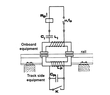
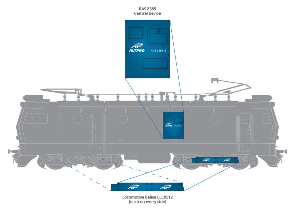
The autostop system consists of train borne and track side part (Fig. 2). The purpose of the system is to prevent the passage of the train over the point of the track if certain conditions were not met. If the train driver does not respond to certain requirements which are needed in the specific moment, the infrastructure part of the system influences the locomotive part and stops the train by emergency braking.
At locomotive part of the system, locomotive balise produces alternating electromagnetic fields of 3 frequencies – 500 Hz, 1000 Hz and 2000 Hz. If this field is found above the active track balise whose resonant frequency matches one of 3 frequencies of the locomotive balise, there is a transfer of information from the track balise to locomotive balise. As there are 3 frequencies, all of the 3 have certain roles:
2000 Hz influence:
- Immediately activates emergency braking
1000 Hz influence:
- Request vigilance from driver
- Activates speed restriction (vehicle slowing down required)
500 Hz influence:
- Speed control in the point of detection.
Track balise is constructed in a way of parallel resonant circuits. They do not use any outside power supply.
For the track balise to be inactive, it is necessary to short circuit a certain resonant circuit. The installation does not require special cabling.
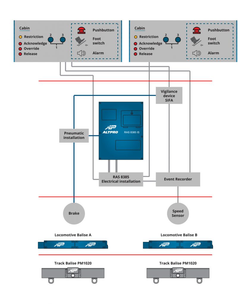
Other parts of the system:
- speed indicator
- speed sensor
- pressure sensor in central brake line
- testing device for locomotive and track balise and central device.
2.1. Train borne equipment
The main components of locomotive part of INDUSI system produced by ALTPRO are:
- RAS 8385 central autostop device which consists of logic part, frequency generator, electro-pneumatic part, influence detector and event recorder.
- Locomotive balise LLC0512 with resonant frequencies 500, 1000, 2000 Hz.
2.1.1. Central device RAS 8385
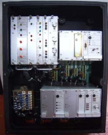
Central device RAS8385 consist of:
- braking unit
- DC/DC converter with high efficiency and availability
- three-frequency generator type GSM0512 for powering the locomotive balise
- module RE4 for simple measuring of the release currents without disconnecting of the device
- for connecting the system to the railway vehicle robust industrial connectors are used
- dead man’s control device (as a totally independent device from ATPS)
- event recorder unit which can be used for registration and monitoring also some other subsystems of the railway vehicle and some vital signals and information (dead man’s control unit activation, breaking pressure, control of the breaking pipeline, cabin activation, direction…).
- module for rail wheel lubrication system.
All parts of AUTOSTOP system have an independent power supply.
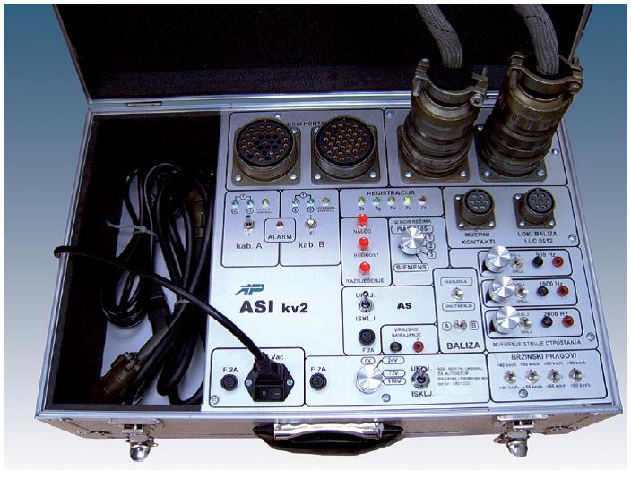
Testing device ASI is also developed, and it enables the testing of the central devices from all manufacturers of INDUSI based systems (ALTPRO, SEL, SIEMENS), (Fig. 5).
2.1.2. Locomotive balise
Frequency generators provide a continuous signal of 500, 1000 and 2000 Hz for locomotive balise. At the moment when locomotive balise is situated above track balise (500, 1000 or 2000 Hz), inductive coupling causes the drop of one of the resonant current in the locomotive balise due to the influence of a parallel resonant circuit of track balise which is active, while two other resonant currents in the locomotive balise stay unaltered. This drop of resonant current is detected in the central device RAS 8385 which automatically conducts train driver check, speed check and if necessary – emergency braking.
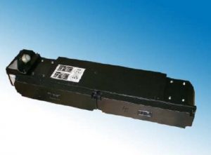
With continuous development of AUTOSTOP product by ALTPRO, it was upgraded in design and technology. Locomotive balise LLC0512 is developed to the level where maintenance is practically unnecessary which is demonstrated by 15 years of use, with no problems in exploitation such as electrical damage or voltage brake down on the coil or capacitor block due to over voltage or moisture.
Regarding the connection, ALTPRO produces locomotive balises with connection from the top (tilted) and from the rear side (straight) according to the needs of the user. Complete functional compatibility was also achieved with other manufacturers’ devices and ALTPRO products are used as a substitute on vehicles that originally had other locomotive balises installed.
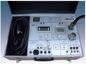
LMI device is used for testing the balises.
3. Trackside part of the system
Track balise is encased in waterproof casing with IP68 rating. Internal components are encased in special epoxy mass and they are resistant to vibrations, moisture and other atmospheric conditions. Connection cable is connected to the locomotive balise through a gland and on the locomotive balize the wires are connected by screw terminal connection. Track balise is mounted on the track with mounting brackets. For the balise to function properly, it is needed to properly adjust the height (distance between the upper surface of the balise and the top of the rail) and side distance from the track center to the inner side of the rail.
Track part of AUTOSTOP system includes track balise with 500 Hz resonant frequency and combined balise with resonant frequencies of 1000 Hz and 2000 Hz. Track balises are passive parallel resonant circuit which means they do not use any external power supply. The balises are mounted on the right side by the track in the direction of the train movement.
Track balise is to be activated by certain contacts of the control relays activated by certain aspects of the signal lights which are installed in the relay signal block. Closed contacts deactivate track balise and open contacts activate the balise. Balise (track magnet) 1000/2000 Hz has three connections for two combinations of the contacts. If both are closed, track magnet is inactive. If one is open, resonant circuit 1000 Hz is active, and if both are open then resonant circuit 2000 Hz is active.
3.1. Track balises
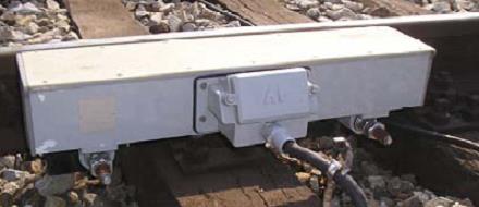
Track balise type PM1020 is a combined track balise which can be set in 3 states – 2000 Hz active, 1000 Hz active and inactive state. It is used for main signals and distant signals and it is activated depending on the signal state. Track balise PM500 is used as a speed control element for station protection.
One of ALTPRO innovations on its track balises is the feature which enables the track balise to report the control center about its status. Track balise, besides 3 basic terminals for activation and deactivation, has additional terminals where connection cables are connected. Those cables are used for detection if the balise is removed from the tracks. It is a completely energy independent system which requires no power supply but it does require additional cabling with one conductor pair.
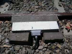
This system can network more signals in a way that removing one balise influences the state of the previous signal. This is an efficient way to detect the act of vandalism as it occurs. Usual controls, measurements and testing of trackside equipment by authorized maintenance personnel are still required for the whole system to work properly. Some railways are preserving their balises from vandalism by concrete blocks. (Fig. 9).
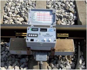
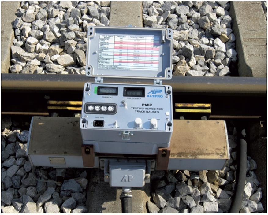
For testing and maintaining track balises many clients in the world use PMI2 device (Fig. 10) which can test the balises from all 3 world producers: ALTPRO, SIEMENS and SEL (Thales).
4. Advantages of implementing ATPS AP autostop
Complete ATP system; Longevity, reliability and quality; Long guarantee period; Independent power supply of all AUTOSTOP components; Low price of the whole system; Complete testing equipment; Quick and simple customer training for maintenance; This solution ensures that all safety systems in the locomotive are placed in one casing (“Dead man’s” control system, event recorder, central AUTOSTOP device, rail wheel lubrication)
5. Certificates
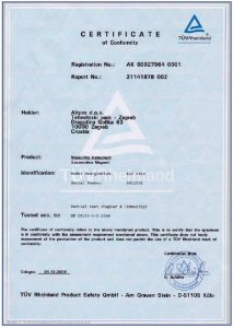
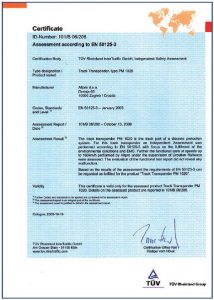
Locomotive and Track balises are tested according to new EN standards in the leading certification institution TÜV Rheinland and currently only ALTPRO has this certificates for this kind of product worldwide.

6. Conclusion
Taking into account the number of the EU countries (railways) that use INDUSI ATPS, we can consider INDUSI as the main ATPS for conventional railway lines and it still offer a high level of safety and reliability with relatively low investments (taking into account both – new projects and maintenance). It is necessary to mention that may railways all around the world still have not any kind of the train protection system. In our region these countries (railways) are: Macedonia, Albania, Greece, Bulgaria… In railways with a speed limit of 160 km/h this ATPS shows really good performances related both safety and availability and life cycle performances. On the Deutche Bahn (German Railways) which we consider as modern and developed railways, this ATPS is still obligatory ATPS on all the vehicles and it will be for a long time in the future even some new technologies are coming to the railways (ETCS). New, modern systems, which are to be used for high-speed applications (more than 160 km/h) are used basically in passenger traffic but the biggest part of the whole traffic is freight traffic. By these reasons we consider that ATPS based on the INDUSI principle with some technology upgrades will be a very interested ATPS both, for installation on the industrial and traffic corridors and traction vehicles, and for refurbishment and maintenance of the railway vehicle and infrastructure on which the INDUSI ATPS is already installed even more than 30 years.
References:
- Poslijediplomski specijalistički studij «Željeznički elektrotehnički sustavi», Točkasti sustavi signalizacije (Lokomotivska signalizacija), Analiza rada točkastog AS sustava, Sustavi kontinuiranog prijenosa informacija
- Technical description RAS8385, User documentation, ALTPRO d.o.o. Zagreb
- Technical description LLC0512, User documentation, ALTPRO d.o.o. Zagreb
- Technical description PM1020, User documentation, ALTPRO d.o.o. Zagreb
- Technical description PM500, User documentation, ALTPRO d.o.o. Zagreb

