
Abstract: Different solutions and applications related to modernization and upgrading of the already existing level crossing protection systems are presented in this article, in terms of replacing the old train detection systems with the new ones (based on the state-of-art modern train detection solutions) designed for SIL4 safety level according to the standards EN 50126, EN 50128, EN 50129, EN 50121-4, TS 50238-3… In the article, ALTPRO presents its worldwide experience in modernization of different level crossing protection systems by its Multi-section Digital Axle Counter System BO23, Train Detection System TDR14 and Electronic Treadle UTR/ITR. This presentation can be very useful for the railway infrastructure managers in order to consider how to increase reliability, availability and safety of the already existing level crossing systems with very low investments.
Keywords: level crossing, train detection, safety, SIL4
Different kinds of train detection devices used for switching on/off the level crossing protection systems
There are many different kinds of train detection devices that have been used for automatic switching on/off the level crossing (LC) protection systems in Europe and worldwide. Train detection devices that are still in operation and are also used for new LC installations in European and other countries are shown on figure 1. Devices in 7 examples in figure 1 can be grouped by the following criteria:
- By the object of detection: wheel detectors / treadles (example 1) and vehicle detectors (examples 2…7)
- By length of detection area (for vehicle detectors): short area detectors (usually a few meters to 30m, loops or short joint-less track circuits, examples 2 and 3) and long area detectors (from the switch-on point to the road area, usually 500m…2km, examples 4…7)
- By the principle of operation: track circuits (examples 3…5), inductive loops (example 2), mechanical / magnetic / electronic treadles (example 1) and axle counters (examples 6 and 7).
Which kind of train detection is mostly used on the level crossings of certain railway (in certain countries) depends usually on historical reasons. For example, in region of ex. Yugoslavian countries, first signalling projects after the World War II were made by Siemens and SEL, Germany, and they mostly used Siemens magnetic wheel detectors / treadles (Magnetik Schienenkontakt) for level crossings. This resulted in the situation that today most of the LC protection systems in this region operate using single or double treadles, like in the 1st example on figure 1. Later, with the development of electronic devices, they added short joint-less audio-frequency track circuits (AFTC) for detection of the train stopping on the road area (since the treadle may or may not detect the stopping of the train, depending on where the wheel stops).
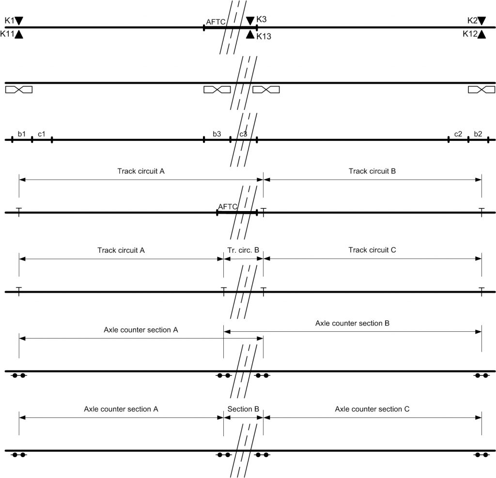
During expansion of railway signalization in Russia and ex. Russian and East European countries the LC protection systems were equipped with long track circuits, usually with increased safety by pulse coding. So today most of the LC protection systems in these countries operate using 2 long track circuits, like in the 4th example on figure 1. Similar situation is in North America; the most common solution for train detection on level crossings is using 3 consecutive track circuits (the 5th example on figure 1).
With the growth of electronic technology, many railway equipment producers developed certain train detection devices that can replace old solutions – treadles (mechanical / magnetic) or track circuits. New electronic detection devices can be applied even on the old (e.g. a relay) LC protection systems, without replacing the whole LC system (replacing only the train detection devices). In case of mechanical or magnetic treadles, the LC protection systems provided for operation with treadles can use electronic wheel detectors or inductive loops (2nd example on figure 1). The LC protection systems provided for operation with short track circuits can use short joint-less electronic track circuits, inductive loops or short axle counter sections. The LC protection systems provided for operation with long track circuits can use two long axle counter sections with overlapping over the road (6th example in figure 1), or 3 consecutive axle counter sections (7th example in figure 1).
Replacing the mechanical and magnetic treadles with electronic double wheel detectors
On Croatian Railways, there are more than 1000 magnetic treadles in operation on level crossings. On some local lines, there are even mechanical treadles still in operation. Those treadles are already almost 40 years in operation; their reed relay contacts are worn out and permanent magnets on magnetic treadles have lost the required characteristics. Therefore, in 2007, company ALTPRO developed the electronic double wheel detector UTR/ITR [1] and started to replace magnetic and mechanical treadles on level crossings. Since the wheel sensor ZK24-2 of the detection system UTR/ITR contains two completely independent and galvanically separated sensing heads, as well as the indoor relay interface module UTR245/ITR245, one double wheel detector UTR/ITR replaces two magnetic or mechanical treadles. For safety reasons, the switch-on point of the LC contain usually two magnetic treadles, the one on each rail; now they are replaced with only one double wheel sensor attached to only one rail, which is much easier to maintain, especially during track reconstruction / grinding. A typical application of double wheel detectors UTR/ITR on LC protection systems that have double control structure (A and B control system) and used two magnetic treadles per switch-on/switch-off point is shown in figure 2.
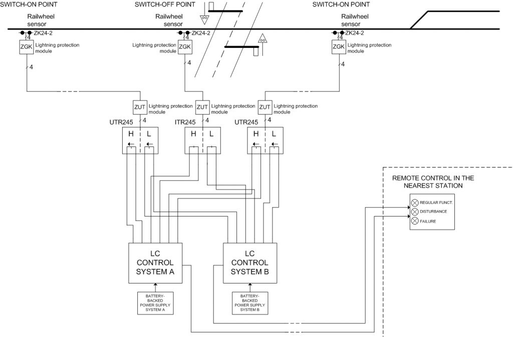
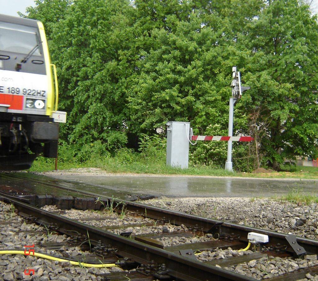
Since mechanical or magnetic treadle provides NO or NC contact (depending whether switches the LC on or off) to the LC control system, double wheel sensors are connected to relay interface modules UTR245/ITR245 in the LC house that provide relay contact outputs [5]. It is a big advantage that this relay contact is now located in the LC house (not on the switch-on point), because the short circuit in the trackside cable cannot cause the hazardous failure (contact permanently closed, independently from train passage). Double wheel sensor ZK24-2 installed instead of 2 magnetic treadles on one level crossing in Croatia is shown on figure 3. On the other/closer rail on the figure there is still one magnetic treadle that is being removed (disconnected from the system).
Today, several hundreds of magnetic and mechanical treadles are replaced with double wheel detectors UTR/ITR on level crossings in Croatia, Serbia and other neighbouring countries.
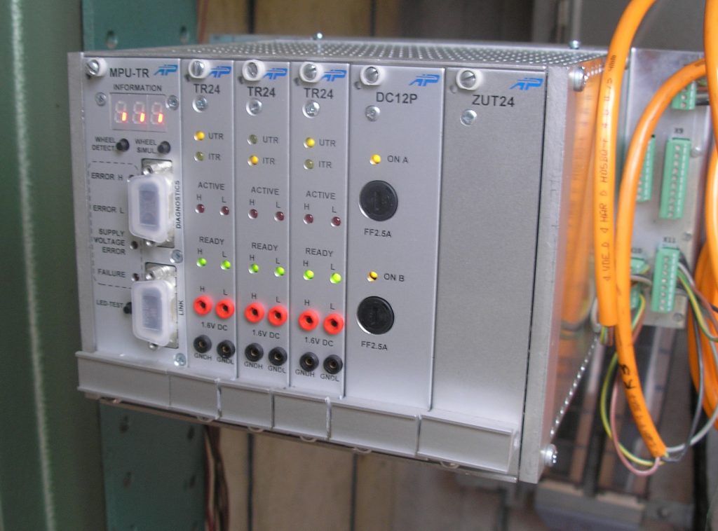
In recent years company ALTPRO developed an upgraded type of electronic wheel detector, the device TDR14 [2], with microprocessor based indoor evaluation module (figure 4). Except additional feature of event log memory of passed trains, some other useful functions were added to train detection device TDR14. One of them is a unidirectional/bidirectional mode of operation. In unidirectional mode of operation the double wheel detector provides fail-safe activation of both detection channels in only one train movement direction; for the opposite train direction both detection channels stay in the basic state (no reaction). In this way, the double wheel detector TDR14 can replace the old SILEC mechanical unidirectional pedal/treadle, which is also still in use on many LCs in Europe. TDR14 can also be applied as a train detection device for new microprocessor LC protection systems, since it is designed and certified for safety integrity level SIL4 (TÜV Rheinland, Germany). The indoor unit of wheel detector TDR14 has a microprocessor voting structure 2-out-of-3 and can evaluate signals from up to 3 double wheel sensors ZK24-2.
Replacing the long track circuits with axle counters
Most of the LC protection systems in the Slovak Republic are old relay based level crossings that use two long track circuits with insulating joints for train detection. These track circuits are AC 25Hz with pulse coding (approx. 2Hz) performed using a motor with eccentric part on the axle to synchronize the transmitted and received pulses. Since this motor continuously rotates for >30 years, track circuits are now very difficult for maintenance. Besides, there are also typical track circuits problems present; change in receiving voltage during changes in track/ballast resistance (e.g. during presence of snow and salt for snow melting on the roads), rust on rails on local lines, etc. Railways of Slovak Republic decided to replace these track circuits with axle counters and ALTPRO proposed solution with two axle counter sections overlapping over the road.
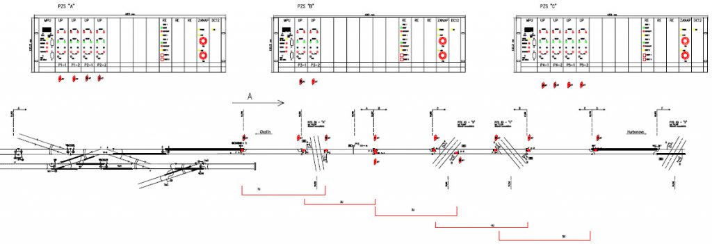
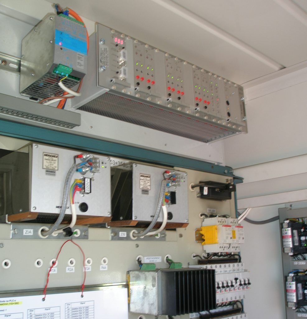
Figure 5 shows the project document for application of ALTPRO axle counters BO23 on 3 relays based LC protection systems on the Railways of Slovak Republic instead of previously used track circuits. The red lines below show the length of each axle counter section; each of 3 LCs is controlled by 2 axle counter sections with overlapping over the road. In each LC house there is one multi-section axle counter indoor unit / evaluator BO23-UNUR [3] that controls 4 counting points (figure 6) on single track (2 sections), or 8 counting points on double track lines (4 sections). The use of two axle counter sections per track eliminated both long track circuits (together with insulating joints, which is better for traction return current) and short audio-frequency track circuit across the road area (the 4th example on fig. 1), since the axle counter sections overlap over the road and detect the train stopping on the road area.
Using the axle counters BO23 instead of track circuits significantly increased the safety of the old LC protection systems, since the axle counter BO23 is SIL4 certified (TÜV Rheinland, Germany) and the indoor unit BO23-UNUR has a microprocessor voting structure 2-out-of-3.
Replacing the short joint-less track circuits with axle counters
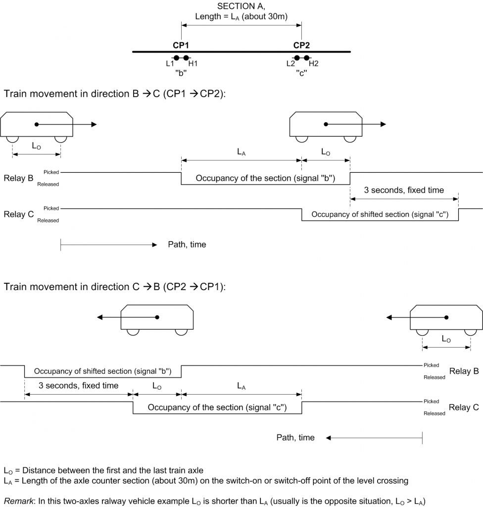
In recent years there were many electronic LC protection systems installed on Croatian Railways and other railways in the region, which use two adjacent short joint-less track circuits (about 2×15m) for switching on/off the LC (the 3rd example in fig. 1). Although those track circuits do not need insulating joints, a few years of exploitation of such equipment showed typical problems of track circuits application; many disturbances in LC operation on low traffic density local lines with light passenger trains, a lot of rust on the rails, and disturbances in LC operation caused by the traction return current of locomotives with switching converters that disturb the signal of track circuit. Croatian Railways decided to replace those short joint-less track circuits with devices of some other detection method, but with the same output of two consecutive occupancy signals (designated as “b” and “c” on 3rd example on fig. 1), so that the software of the electronic LC protection system wouldn’t have to be changed. ALTPRO had made a project of replacement solution [4] with axle counters (fig. 7). Short track circuits that are being replaced are designated in red colour on figure 7 (“EOC-detectors” – 2 consecutive track circuits with common transmitter in the middle and two receivers 15m on each side). Axle counter BO23 equipment with 2 counting points (1 section) for replacement of both track circuits on each switch on/off point is designated in green colour. An additional relay interface that was necessary to develop for the connection to the existing LC protection system is designated in blue colour on figure 7. Since two consecutive track circuits are replaced with only one axle counter section, ALTPRO developed the relay interface with B and C output relays; by the use of optocoupler directional axle counter outputs of train passage on each counting point appropriate relay (B or C) state is changed when the 1st train axle passes the 1st or the 2nd counting point of the section.
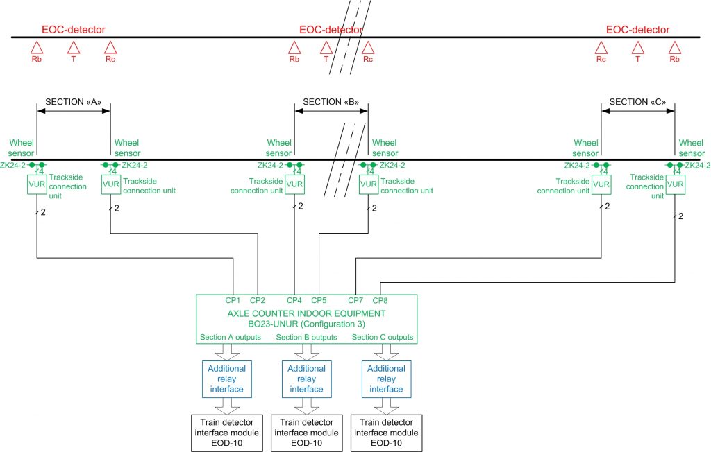
In this way, two occupancy signals “b” and “c” are achieved in the correct sequence during the train passage (figure 8), the same as for the train passage over the two consecutive track circuits. The benefit of this simple relay interface development was that only one axle counter section with two counting points (instead of 2 sections with 3 counting points) can be used for replacement of 2 consecutive track circuits on switch on/off point of LC.
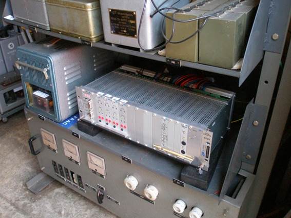
Since the new components were applied within the electronic level crossing, the whole LC protection system with axle counter BO23 and relay interface needed to be assessed for safety. Axle counter BO23 already had the SIL4 certificate and for the relay interface, safety analyses and safety case were made. Safety assessment of LC with those devices was then performed by TÜV Süd, Germany, and Croatian Railways commissioned several dozens of LCs with track circuits replaced by the axle counter BO23 and relay interface (figure 9). Further exploitation of those LCs showed much less disturbance in operation and improved reliability and safety.
Conclusion
Through several years of exploitation, electronic wheel detectors and axle counters proved themselves as much better and more reliable and safe solution for detection of train for switching the level crossing on/off, in comparison with older devices such as track circuits and mechanical/magnetic treadles. There are many LC protection systems in operation for 20 to 30 years in Europe (mostly relay based, but also microprocessor based) that contain indoor equipment able to operate for 20 more years, but with the outdoor train detection equipment which is at the end of the life cycle. Replacement of the old train detection equipment (mechanical/magnetic treadles, track circuits…) with electronic wheel detectors or axle counters can extend the life cycle of those LCs for 20 more years and improve the reliability and safety of the level crossings.
References:
- Train detection system UTR/ITR Operating Instructions, ALTPRO, Zagreb 2011
- Train detection system TDR14 Operating Instructions, ALTPRO, Zagreb 2011
- Axle counter BO23 Operating Instructions, ALTPRO, Zagreb 2011
- Specific application of axle counters BO23 as a replacement for EOC-detectors, ALTPRO, Zagreb 2011
- ‘New solution for ON/OFF switching of level crossing systems’, Horvat H., Signal und Draht, 6/2007