
Summary: There are many level crossing systems that use punctual double-channel wheel detection for switching on/off the level crossing, usually combined with short audio frequency track circuit, loop or axle counting section for detection of the train stopping on the road area. Today, there are even better ways to activate/deactivate the level crossing, for example using 2 or 3 axle counter sections (per single line) that cover both approaches (from both sides) and road area. However, in both east and west Europe, there are still many older level crossing systems that use punctual wheel detection (without counting axels) for switching on/off the level crossing and most of these level crossings will be in operation for another 10, 20 years or even more. Lots of different wheel detection devices are used on such level crossings: from mechanical treadles and magnetic detectors with reed-relay to electronic inductive wheel sensors such those used in modern axle counting systems. Wheel detection system UTR/ITR based on inductive double wheel sensor ZK24-2 is a new solution either for replacement of mechanical treadles and magnetic detectors, and for implementation in new level crossing systems.
1. Introduction
In southeastern Europe most of the currently installed level crossing systems is old relay-based systems that use punctual double-channel wheel detection for switching on/off. Such level crossings were installed during 1960-ies and 1970-ies, and most of them still use old magnetic wheel detectors with reed-relay produced by Siemens (two detectors per switch-on point on both sides of the road and two detectors per switch-off point), or mechanical treadles produced by Silec. The operation of such magnetic detector is based on the permanent magnetism and good condition of reed-relay contact, which is already in the device, mounted on the rail. In such a long operating time period (>30 years) the permanent magnet looses the strength of the magnetic field and the contact material of the reed-relay is rather worn. The maintenance and repair of the magnetic detectors are every year more difficult and the number of failures is increased in recent years.
As the replacement to these magnetic wheel detectors company Altpro developed the wheel detection system UTR that uses electronic double wheel sensor ZK24-2, already proven in the Altpro’s axle counters BO1 and BO23. Since the wheel sensor ZK24-2 has two separate sensing systems in the same case, one sensor ZK24-2 together with the relay interface module UTR245 can replace two magnetic wheel detectors.
2. Wheel detection system UTR as a replacement for old magnetic detectors
Electronic wheel sensors usually don’t have the same principle of outputting the wheel presence information as magnetic detectors and mechanical treadles; the sensor usually has current or voltage output and magnetic detector has relay contact output. For direct replacement of magnetic detectors with electronic wheel sensors on relay level crossing systems the interface of current or voltage signal to relay contact or optocoupler is needed. Figure 1 shows how one switch-on a detection system (e.g. on the left side of the road) is performed using the wheel detection system UTR.
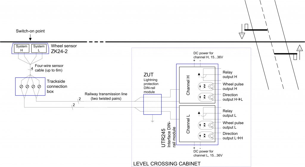
As shown on figure 1, wheel detection system UTR consists of the wheel sensor ZK24-2 on the switch-on point on the track and the interface module UTR245 located at the level crossing housing or cabinet, that provides relay and optocoupler outputs. The lightning protection module ZUT is connected between the sensor and the interface module to protect interface module UTR245 and the rest of the level crossing system from lightning overvoltages. For the connection of indoor and outdoor part of the system (the distance could be up to 2km, depending on the train speed) two wires are used per sensing system of the sensor ZK24-2, 4 wires total. In case of replacing magnetic or mechanical treadles, exactly the same cabling infrastructure is already present, because two treadles are used for switching-on the level crossing (on each side of the road) for safety reasons (OR-logic: activation of any treadle will switch the level crossing on, but if only one treadle was activated, the level crossing system will indicate disturbance). Each magnetic detector was connected via one twisted pair (2 wires), so two twisted pairs already exist between each switch-on point and the level crossing when one wheel sensor ZK24-2 replaces two magnetic detectors.
3. Wheel sensor ZK24-2
Wheel sensor ZK24-2 was developed in company Altpro together with the axle counter BO1 and is used as a wheel detection component in the axle counter type BO23 and BO1, which is in regular operation in automatic block on Croatian Railways for several years. Croatian Railways recently decided to replace old magnetic detectors on relay level crossings and Altpro developed the interface module UTR245 to be able to connect the wheel sensor ZK24-2 to the relay level crossing and replace the magnetic detectors.
The very important requirement is that the sensing systems (H and L, see figure 1) in the sensor are completely separated, both functionally and galvanically, to be able to replace two magnetic detectors with one sensor ZK24-2. Each sensing system works independently and is based on the inductive principle with different frequency of the magnetic field for each system. Electronic circuitry for wheel signal evaluation on each system is already integrated into the sensor’s case and filled with special compound for water protection class IP68. Two wires of the 4-wire sensor cable are dedicated to each sensing system; each system receives the DC power supply via these two wires and gives the wheel pulse signal to the level crossing system via the same two wires. A signal is provided as a DC current loop with higher current without the wheel presence and lower current when the wheel flange is present above the sensor. The current loop provides very high distance between the sensor ZK24-2 and the interface module UTR245; e.g. with wire diameter 0.9mm the maximal distance is 17.8km.

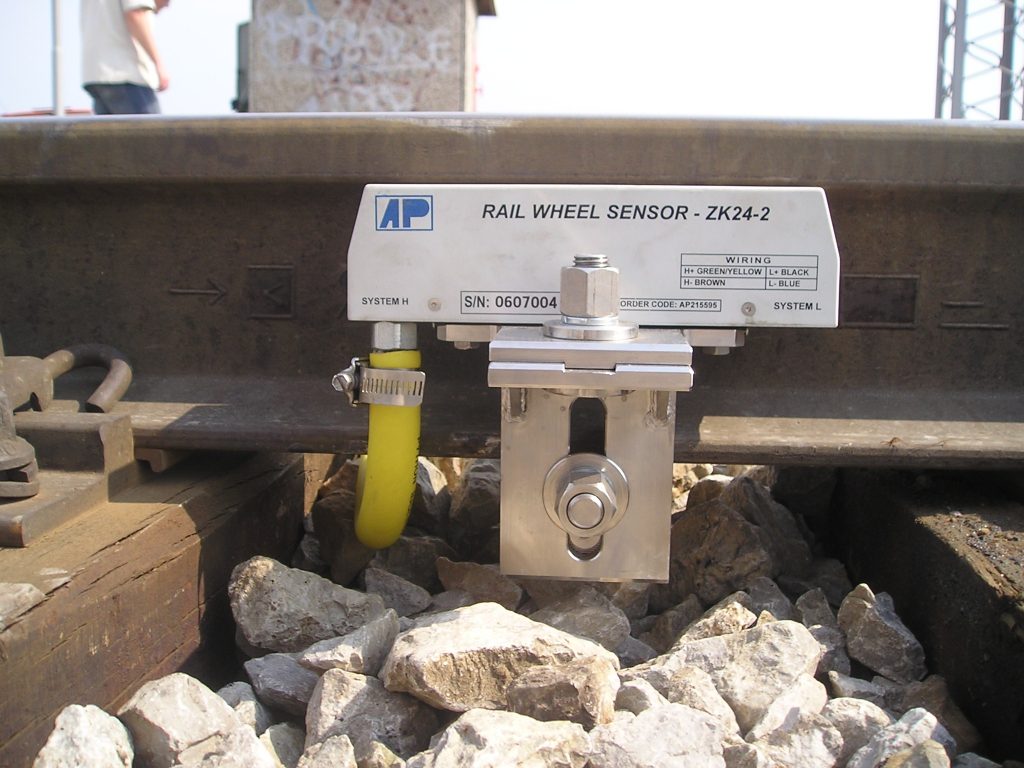
The sensor ZK24-2 is mounted on the inner side of the rail using the universal mounting clamp fixed to the rail foot (figure 2). It is no need for rail drilling and the same mounting clamp can be used on rail types S45…S49…UIC54…UIC60 (including all types between).
The big advantage of the wheel sensor ZK24-2 is very simple and quick installation and maintenance. Installation requires no electrical adjustment (no potentiometers or similar adjustment); only mechanical position adjustment using the plastic template is required. Maintenance is reduced only to six-month period position check using the plastic template. In case the sensor drops-away from the rail for any reason, both systems will output the low current state continuously (fail-safe).
4. Interface module UTR245
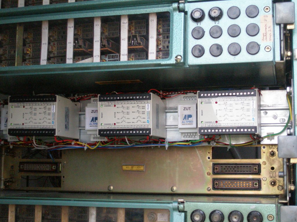
Interface module UTR245 contains two galvanically separated channels that convert a current loop signal from each system of the wheel sensor ZK24-2 to the safety relay and optocoupler output (figure 1). The box of module UTR245 is provided for mounting on DIN-rail (99.7mm wide box) or panel anywhere in the level crossing housing or cabinet. Figure 3 shows 3 interface modules UTR245/ITR245 together with lightning protection modules ZUT (also on DIN-rail) installed in one level crossing housing on Croatian Railways (two double wheel detectors for switching-on and one for switching-off).
There are 3 types of outputs on each channel of the module UTR245: two optocouplers and one safety relay. One optocoupler provides a pulse for each wheel that passes the sensor. Safety relay operates on the first train wheel and returns to the basic state with time delay (5s; adjustable on user’s request) after the passage of the last wheel. The other optocoupler operates the same way as the safety relay, but only in one direction of a train movement. The appropriate optocoupler on the other channel operates only for the other direction of a train movement.
Safety relay contact output is suitable for connection to older relay level crossing systems; using the relay outputs wheel detection system UTR can directly replace two magnetic or mechanical treadles, which also have relay contact as output. Two galvanically isolated potential-free changeover contacts of the safety relay on each channel are provided on interface module UTR245. Since the wheel detection system can be used either for switching-on and switching-off the level crossing system, there are two types of the interface modules: UTR245 and ITR245. The only difference between these two types of modules is that module UTR245 has safety relays picked-up in the basic state (when there is no wheel above the sensor), and module ITR245 has safety relays released in the basic state. Wheel detection system (UTR) with interface module UTR245 is therefore provided for switching the level crossing on, and wheel detection system (ITR) with interface module ITR245 is provided for switching the level crossing off.
Interface module UTR245 also provides the optimal power supply for the wheel sensor ZK24-2 (48V DC, separate power for each channel). Power supply for each sensing system on the sensor is galvanically isolated from the main channel power (15V…36V DC) and has continuous short-circuit protection.
5. Application
Except the replacement of the mechanical and magnetic treadles (which was the main reason for development) mostly used on relay level crossing systems, the wheel detection system UTR can be applied in newer microprocessor level crossing systems. There is pulse optocoupler output on each channel that gives a pulse for each wheel passage over the sensor and microprocessor system can use these outputs to count axles, to determine the movement direction, etc. Even the train movement direction determination doesn’t have to be implemented in the software of the system because the interface module UTR245 also has direction dependent optocoupler outputs. One direction output activates only for train movement from system H to system L of the sensor ZK24-2, and the other direction output activates only for train movement from system L to system H. Using both direction dependent optocoupler outputs and pulse optocoupler outputs on both channels (total 4 digital inputs on microprocessor system per wheel detection point) can make the software of the level crossing system very simple and safe.
There are many different hardware structures of the level crossing systems; many systems have two completely separated hardware channels including the power supply system and batteries. Two power supply channels are on some types of level crossings galvanically isolated. The wheel detection system UTR has both in wheel sensor and in interface module two galvanically isolated channels, so one channel can be connected to the first power supply of the level crossing, and the other channel can be connected to the second power supply. Example to this are relay level crossings on Croatian Railways; they have two completely separated systems with separate power supply for each system, and one magnetic detector is provided at the switch-on point for each system (two detectors total per switch-on point). Thanks to galvanic separation of channels in wheel detection system UTR, both magnetic detectors can be replaced with only one wheel sensor ZK24-2 and interface module UTR245.
There are many other signalling systems where the wheel detection system UTR can be applied, both safety systems and non-safety systems. Very practical solution is to use the wheel detection system UTR for train announcements for the station. The train announcement is usually required to announce the train (by the bell and light) to station operator when the train is 3km close to the station, but only in the direction towards the station, not in the opposite direction (departing). One direction dependent output on the interface module UTR245 can be directly used for the train announcement because the output will activate in only one train movement direction.
6. Conclusion
When replacing old mechanical or magnetic wheel detection devices with wheel detection system UTR there are several benefits:
- Much more simple maintenance and much lower failure rate (no mechanical moving parts and no permanent magnetic field)
- Much longer life cycle of the output safety relays (relay activates on the whole train, not on each axle)
- More reliable fail-safe function in case of dropping-away from the rail
- Less equipment on track (one wheel sensor ZK24-2 replaces two magnetic/mechanical wheel detectors)
- No speed limit to 160km/h (as by usage of magnetic detectors) since the maximal train speed for sensor ZK24-2 is 350km/h
- Short-circuit protection, i.e. fail-safe action in case of short-circuit of the twisted pair on track; magnetic detectors with reed-relay contact on the track can come to permanent unsafe state in case of short circuit of the twisted pair.
The replacement of older devices and the possibility of application in new microprocessor signalling systems make the wheel detection system UTR/ITR very universal in railway signalling.
References:
- Train detection system UTR/ITR Operating Instructions, Altpro, Zagreb 2006
- Multiple Applications with a Single Subrack of Multi-section Axle Counter BO23, Hrvoje Horvat, Signal+Draht 07+08/2006