There are many small railways in Europe operating regional passenger and freight transport. Sometimes they are physically separated from main lines due to narrow gauge, which is often a case in Austria. Their specific characteristics are: short trains, many small stations, short distance between stations and short headway between trains. Due to limited financial resources for new investments, they seek cheaper signalling solutions. This article describes a technically advanced and cost effective solution of the company Altpro for complex level crossing situations of Zillertal railway. Several level crossings are now equipped there with SIL4 electronic protection system RLC23 with train driver’s signals and interface to the computer-based train control system.
1. Specific traffic situation on the local small Railway
The Zillertalbahn operates the local railway between Jenbach and Mayrhofen in Austria. The line length is about 32km, with narrow gauge 760mm track. In the Zillertal valley, there are lots of small towns and villages along the line, and therefore many level crossings and train stations. Here are the main characteristics regarding the level crossings on Zillertalbahn railway:
- A lot of level crossings, often with short distance between them (<200m)
- Most of the level crossings are located close to the station or in the station area
- 30 minute headway between trains – 15 minutes during some periods of the day
- As the stations are small (short tracks), the level crossing activation point is usually located on the opposite side of station, on the open line
- The stations are not equipped with interlocking and there are no home/exit signals in stations (the whole railway is protected by train control system with remotely operated turnouts)
- The stations and train stops are not supervised by station operator or any other person for traffic operation
- Level crossing is often located very close to the turnout in station, and the space on the rails for deactivation elements is very narrow (e.g. <1m)
- Most of the trains are short, but exceptional long trains can stop in station across the level crossing
- Two successive trains are possible in the level crossing area
- Different rail profiles: S49, Xa, XXIVa, UIC 54, S33
- Historical rolling stock with spoke wheels or very small wheel diameters.
For automatic protection of train routes Zillertalbahn uses computer-based train control system (Zugleitsystem) from RDCS. The system controls all train routes (radio-based control) from the operational centre. The trains are located via balises and GPS. Orders and indications about the route are sent over a radio data network to the train and are displayed as a cabin signalization to train driver. Voice radio is used only in emergency situations and as a back-up level. However, the system doesn’t contain trackside light signals (except signals of turnouts position), but only the fixed mechanical boards. One of the potential train stopping points designated by trapeze-board fixed mechanical signal (Trapeztafel) is a point at the entrance to the station, which actually corresponds to the point of a home signal in conventional interlocking systems.
Since there are no interlocking signals on the line, the technically protected level crossings on Zillertalbahn contain their own train driver’s indication signals (Eisenbahnkreuzung Überwachungssignale, EKÜS) on braking distance and repeater driver’s signals directly before the level crossing (LX). The most common principle for the driver’s indication signal is to show the aspect “Route over the level crossing allowed” only after the LX activation, which means that activation point is located on at least a sighting distance before the driver’s signal (500…650m from LX on Zillertalbahn). The activation point distance can only be shorter if a different operation of train driver’s signal is used (see chapter 2, “supervision of LX availability” – activation point on at least 395m), or in exceptional cases (lower speed, slope).
Such a long distance from activation point to LX can often have in its range the train stopping point on station entrance. If the train for some reason has to stop at that point, possibly the LX would deactivate automatically after defined timeout, before the train reaches the LX. In case of a conventional interlocking system, this situation would be easily solved by the connection/dependency of the LX with the interlocking home signal – the LX would activate only when the home signal doesn’t show the Stop aspect. However, without interlocking and home signal, the different methods should be applied. The technical solution from Altpro is explained further in the article.
2. Various modes of train driver’s indication signals operation
According to the Austrian Level Crossings Act (Eisenbahnkreuzungsverordnung, EisbKrV), the train driver’s indication signal operation explained in the previous chapter is considered as “supervision of proper LX functioning” (Funktionsüberwachung). The aim of this method is to show the train driver both whether the LX is functioning properly for the current train route (that the road signalization is activated properly, and possibly that the barriers started to lower, if used) and that no fault is present on LX equipment. Only when both conditions are met the driver’s signal shows the aspect “Route over the level crossing allowed” (flashing white light); otherwise the driver’s signal is dark, and after the train passage over the LX and deactivation of LX it becomes dark again.
Another method of train driver’s indication signal operation allowed by “EisbKrV” is based on the “supervision of LX availability in correct operation status” (Verfügbarkeitsüberwachung). In this method, the driver’s signal continuously shows the flashing white light (aspect “Route over the level crossing allowed”) to the train driver (even in the basic state, without train passage) and the signal turns dark/off as soon as the LX protection system detects a fault and is no longer in correct operation status. As the modern microprocessor LX protection systems can achieve SIL4 safety integrity level with double or triple processing channels, there is very low probability of hazardous combination of more than one fault occurrence during the train passage, so there is no need for driver’s signal to show the proper LX functioning for the current train passage; it is enough to show the general LX correct operation status. The driver’s signal with such operation is also located on braking distance from the LX, and since flashing white light of the signal doesn’t depend on LX activation by train, the activation point can even be located behind the driver’s signal (depending on calculation related to clearance time of the road traffic), i.e. on shorter distance than the braking distance. This provides the possibility to avoid having the train stopping point on station entrance within the range of LX activation section; the beginning of shorter activation section can come behind the train stopping point, so when the train stops on that point it will not activate LX yet. The closing time of the LX is rather shorter as well, comparing the closing time of LX when a conventional driver’s signal with “supervision of proper LX functioning” (Funktionsüberwachung) is used.
Figure 1 shows the layout of one level crossing in station Strass on Zillertalbahn. For direction from Jenbach side, the train driver’s indication signal EKÜS1 with “supervision of LX availability in correct operation status” (Verfügbarkeitsüberwachung) is used and activation wheel sensor K1 is located behind the driver’s signal EKÜS1 (on distance shorter than the braking distance) and behind the train stopping point on station entrance (trapeze-board / Trapeztafel). For direction from the Mayrhofen side (on the right) there is only a designated “virtual activation point”, because most of the trains stop in station Strass and activation from the open line on the other side of the station is not required for regular passenger trains. However, for trains that don’t stop in station Strass the LX will be activated by the train control system (Zugleitsystem) pulse, given when the locomotive comes exactly to the designated point of track, and the driver’s signal EKÜS2 for that direction is operating as for the “supervision of proper LX functioning” (Funktionsüberwachung).
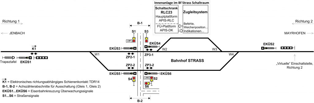
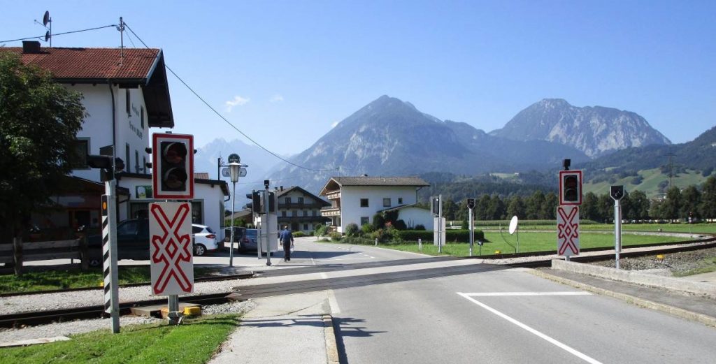
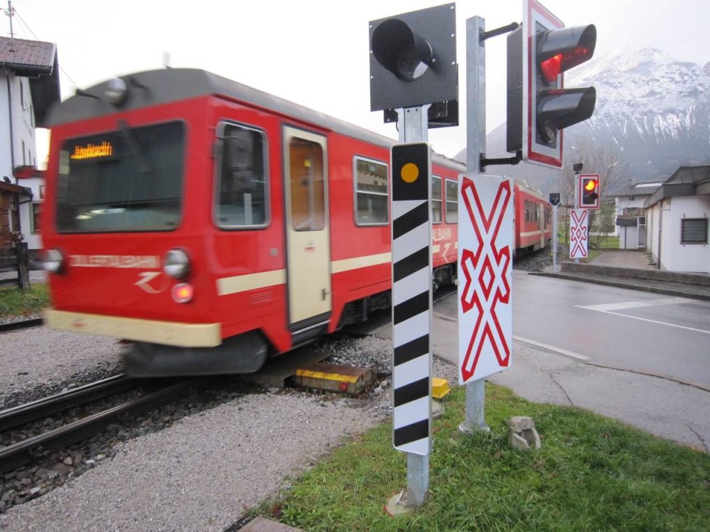
The level crossing in station Strass is protected by LX protection system RLC23, produced by company Altpro. Thanks to the LX interface to the train control and turnouts protection system, trains that come from direction Mayrhofen will automatically activate the LX on the “virtual” activation point on the open line, or after stopping in station Strass (before departure further to Jenbach), depending on train number, i.e. whether the train stops in the station Strass or not. This way the road traffic is always interrupted in the shortest possible time period. The LX is open for road traffic when the train from Mayrhofen comes to the station and stops; the LX activates only when the train needs to depart further to Jenbach, which can be triggered in 3 ways: remotely from the operational centre in Jenbach (over the train control system), by pressing the pushbutton on the station control tableau (“Handeinschaltung”) for departure from appropriate track, or directly from the locomotive (train cabin) by train driver using radio-transmitter switching. Depending on departure track, appropriate driver’s signal repeater EKÜS4 or EKÜS6 in front of the LX shows flashing white light after the calculated time delay, to allow the road users to clear the crossing safely. Figure 2 shows the road signals and train driver’s signal repeaters on the level crossing in station Strass.

The turnout W2 in station Strass is only approx. 1m away from the road area; this space is large enough to install the wheel sensor ZP3-1 of the axle counter for LX deactivation (figure 3), but there is not enough space for installation of the inductive loop for deactivation. Therefore, solution for train detection with inductive loops is not suitable for level crossings on Zillertalbahn; the most suitable solution is to use axle counters.
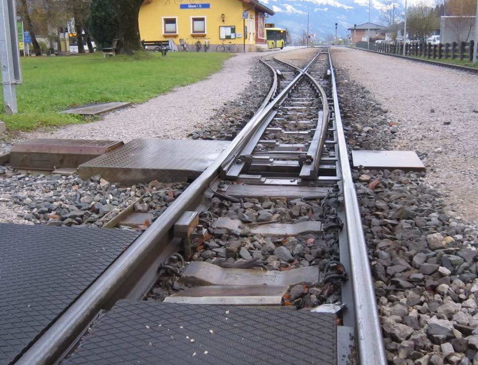
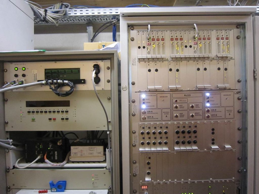
Figure 4 shows the indoor control cabinet of LX protection system RLC23 in the station Strass relay room. The microprocessor control platform APIS-RLC is placed on the top of the cabinet. It is performed as distributed processing system, in voting logic 2-out-of-2, with separate microprocessor module for each group of the outdoor elements (road signals, train driver’s signals, barriers, axle counters…). For the interface/connection with train control system the control cabinet RLC23 uses the slave microprocessor platform APIS-DK (also called “remote control platform”), which is on the other railways usually used for the fail-safe remote monitoring of LX in station and connection/interface to interlocking and/or automatic block system. Since the remote control platform communicates with the main control platform APIS-RLC over the Ethernet connection it can be dislocated from LX hut for several kilometres over fibre optic or DSL line. The complete LX protection system RLC23 is certified by TÜV Rheinland for SIL4 generic application, and additionally for the specific application at the level crossing in the station Strass (for SIL4 as well), since the operating conditions are very specific on Zillertalbahn railway.
For the road signalization the traffic light principle is used with steady yellow (first 4 seconds of train warning) and a steady red light, according to Austrian regulation “EisbKrV”. The LX protection system RLC23 uses Ø 300mm LED-lanterns that comply with standards EN 12368 and DIN VDE 0832-310 (CLC/TS 50509). The audible warning on road signals is performed using electronic bell that doesn’t require mechanical maintenance (unlike mechanical bell). Since the microprocessor system RLC23 contains the real time clock it can be configured to switch the electronic bell to lower sound intensity (–6dB) during the night period, e.g. between 20h and 6h. Figure 5 shows the road signal of RLC23 system with red/yellow LED-light and electronic bell on top during the Zillertalbahn’s diesel-motor train passing the LX.
3. Solution of common activation point and common train driver’s signal for two or more close level crossings
As there are many level crossings on Zillertalbahn with rather short distance between two consecutive crossings, there is a possibility on LX protection system RLC23 to reduce the amount of track elements and costs by having one common activation point using one axle counter wheel sensor, and one common train driver’s indication signal for 2 or more close crossings. In case of extremely close level crossings (several tens of metres) it is even possible to have the common deactivation axle counter section, as well as common control cabinet and LX hut/container. Figure 6 shows the layout of 3 close level crossings at station Schlitters on Zilertalbahn, also protected by RLC23 system.
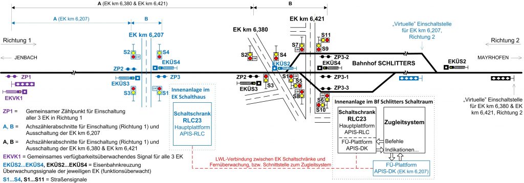
As the level crossings in km 6,380 and km 6,421 (figure 6) are only 41m away from each other, they have the common deactivation axle counter section and are controlled from the same control cabinet RLC23, which in this case drives 11 road signals with yellow/red LED-lights. The protection elements of those 2 crossings are designated in black colour and protection elements of the 3rd LX in km 6,207 (about 180m away from the other 2 LXs) are designated in blue colour. Each LX is from Jenbach side activated by the axle counter section A and deactivated by axle counter section B across the road area, using the separate wheel sensors except the wheel sensor on activation point ZP1, which is common for all 3 crossings (in violet colour). Not to have too great warning time for the LX km 6,380 and km 6,421, the train driver’s signal EKVK1 with “supervision of LX availability in correct operation status” (Verfügbarkeitsüberwachung) is used and therefore the activation point ZP1 can be located on shorter distance than the braking distance. The driver’s signal EKVK1 is also common for all 3 level crossings; its white light is driven by the LX km 6,207, but the white light will not flash (it becomes dark) if any of the control cabinets comes out of the correct operation status, i.e. detects a fault. The control cabinets of all LXs exchange their correct operation / fault statuses through fibre optic network (designated in red colour), according to fail-safe communication principles of EN 50159.
4. Additional LX safety by centralized monitoring, diagnostics and cabin signalization with automatic train stop
Thanks to the central operation of turnouts protection and train control system from the main operator’s room in Jenbach station, all the level crossings on Zillertalbahn are remotely monitored on HMI-monitors in the central office in Jenbach. The LX protection systems RLC23 provide status outputs to the interface module of the train control system, which is further sending the information through Zillertalbahn’s fibre optic network to central office in Jenbach and status of LXs are then displayed on train control system monitors to the operator. The following status information is sent from each LX protection system RLC23 to the train control system: correct operation / fault / disturbance status, activation of road signalization, position of the barriers (if used), LX protected from certain direction (route allowed by train driver’s signal), availability of AC power network, correct voltage of DC battery power, manual disabling of train detection units, axle counter sections occupancy, operation of local manual commands (shunting-switch and local-switch for LX activation), automatic LX deactivation after timeout and enabled reset of axle counters after timeout. Using this information, the operator in Jenbach central office can be aware of the exact status of the level crossing protection system in every moment.
Except the status monitoring capabilities through the train control system, the LX protection equipment RLC23 on Zillertalbahn has a server-based diagnostic system, also performed through the Zillertalbahn’s fibre optic network. Every level crossing protected by RLC23 system has an Ethernet connection to the telecommunication converters to fibre optic network in the nearest station. Through this communication channel every LX is providing the diagnostic data from its event log memory to the central server PC in Jenbach. On the server PC company Altpro installed the server application which automatically reads and saving the event log memory of every LX protected with RLC23 equipment on a daily basis. The application then forms the week-files of the event logs for each LX and stores them into the separate directory dedicated to one year and one level crossing. Furthermore, the server application automatically sends the SMS-message to the mobile phones of several maintenance persons and the email to the train control system operator in case of fault or disturbance status occurrence on any LX. This way the reaction of the operators and maintainers on faults and disturbances is very quick, even quicker than the official way of passing the information from train driver to the operator that the driver’s signal of the LX is dark upon fault occurrence.
Another measure for additional safety that can be performed on the train control system is to transmit the information received from certain LX that the LX is protected (correctly activated) over the radio link to the train driver as a cabin signalization. As the train control system recognizes the exact current position of train on track, at the point of passing the driver’s signal on the braking distance from LX the train control system can perform automatic braking when the LX was not correctly protected (there was no flashing white light on driver’s signal). This can significantly reduce the human error possibility of not observing the driver’s signal by the train driver.
5. Conclusion
The circumstances on local small railways are rather different than on the big railway companies, especially regarding the signalling safety systems including level crossings. However, demands for the safety on level crossings are the same on the small and on the large railways – SIL4. On the example of small Zillertal railway, it is proven that with the modern SIL4 level crossing protection systems in connection with a train control system the similarly high standard of safety can be achieved as with LX protection systems in connection with interlocking. A few years of level crossing protection system RLC23 operation experience on several crossings on Zillertalbahn showed that the system is very flexible to conditions of the local small railways. The suitable application of RLC23 system is there achieved mostly regarding its configurability and flexible interfacing to the interlocking or local train control system.